Unreinforced Roman Hydraulic Concrete
Crushed ceramics (pots, tiles, bricks) were used for many centuries to obtain waterproof plasters for cistern and aqueduct linings, called opus signinum, but the crushing of potsherds was much more labour intensive than just mining river sand. Around 200 BC, crushed ceramics were replaced by Puteolanis pulvis (‘pozzolana’ sands mined from the Phlegraean Fields near Pozzuoli) for the construction of coastal fish tanks (piscinae), as it allowed mortar to cure under water, reason why it is called ‘hydraulic mortar’. Roman hydraulic concrete is the combination of this hydraulic mortar with layers of aggregates (Vitruvius, De Arch., 2, 6 and Pliny, Nat. Hist., 35, 47 & 36, 52-54). The resulting structure is now called opus caementicium.
Although the compressive strength of Roman hydraulic concrete is smaller than that of modern concrete, its longevity, especially in marine conditions, is still a matter of surprise and debate for modern civil engineers. However, recent research indicates that the presence of lime clasts generates a process of long-term self-healing of micro cracks by filling them with calcite[1].
Roman hydraulic concrete ratios and properties are summarised below, from the extensive work of Marie Jackson (in Oleson et al., 2014)[7].
| Ratios and properties |
Concrete with tuff |
Concrete with carbonate rock |
| Lime (calx) (weight %) |
15% | 10% |
| Pozzolana (pulvis) (weight %) |
40% | 30% |
| Aggregates (caementa) (weight %) |
45% | 60% |
| Unit weight dry mix (kg/m3) | 1100 – 1250 | 1400 – 1550 |
| Unit weight hardened concrete (kg/m3) | 1500 – 1600 | 1600 – 1700 |
| Compressive strength (MPa)* | 5 – 8.5 | 2.5 – 5 |
*: 1 MPa = 10 kg/cm2 or 100 ton/m2.
This major innovation in river and coastal engineering was introduced around 200 BC for fish tanks (piscinae) (acc. to Oleson et al., 2014) and further developed in the 1st century BC, when large blocks of hundreds of cubic meters of concrete were constructed under water under the name ‘pila’ (up to 1500 m3 in Nisida, more details in section on Vitruvius’ methods). The oldest known applications for harbour works are at Agrippa’s naval base of Portus Iulius, near Pozzuoli, in 37 BC, and at Cosa (Oleson et al., 2014). This technology (and Puteolanus pulvis that goes with it) was exported to several places around the Mediterranean Sea, such as Pompeiopolis (Turkey), Caesarea Palaestinae Sebastos (Israel), Alexandria (Egypt), Nora (Sardinia) and Iol Caesarea Mauretaniensis (Algeria). Clearly, as hydraulic concrete was discovered near Pozzuoli two centuries earlier, nobody would take the risk inventing another mixture without any certainty that it would provide the same long-term quality, especially as Vitruvius himself stated that Puteolanus pulvis was available only in Italy (de Architectura, 2.6.5). Hence, Roman engineers shipped it over long distances instead of looking for a local substitute.
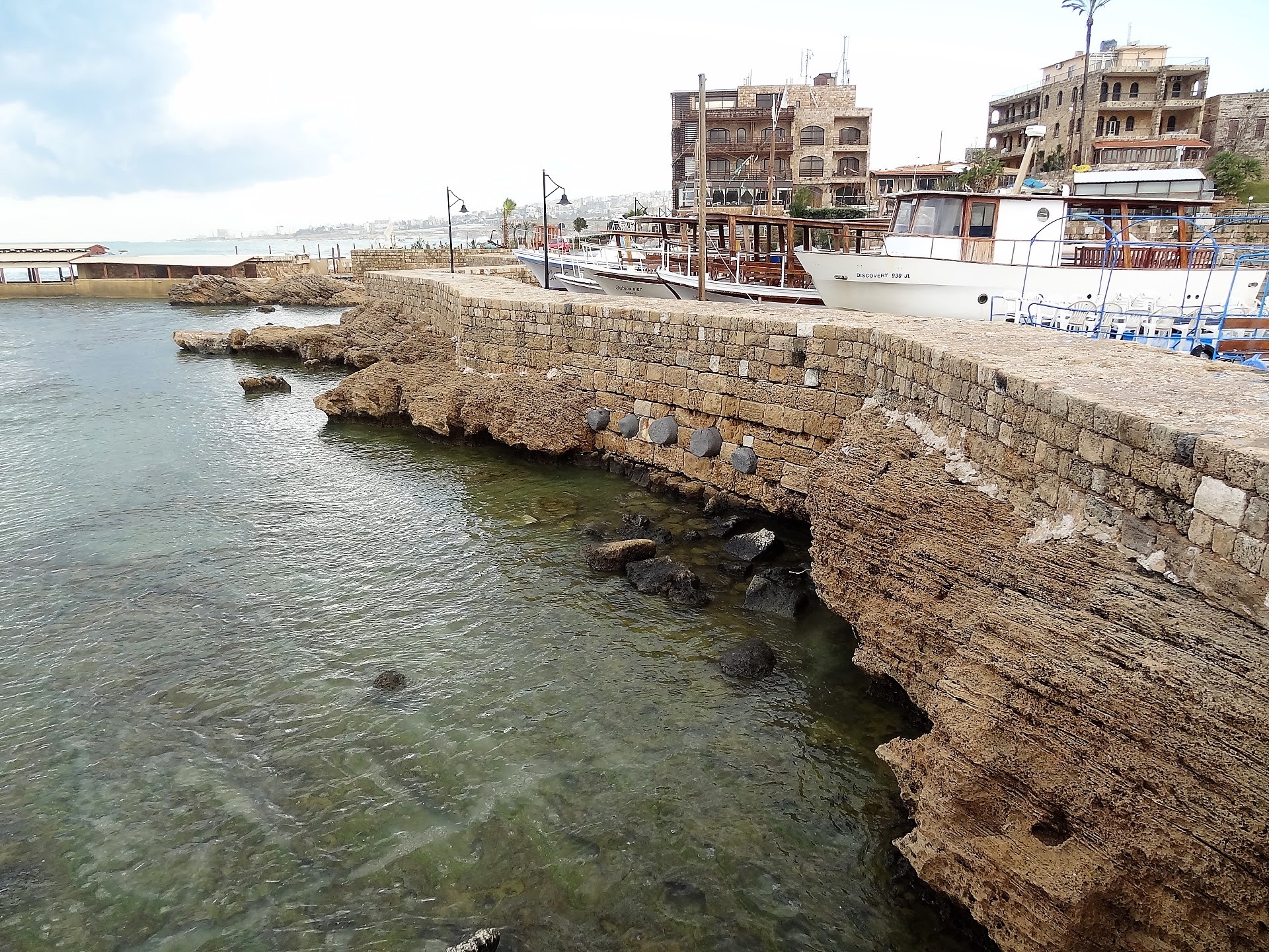
True Roman hydraulic concrete with pozzolana was forgotten during the Byzantine period when pozzolana was replaced by crushed ceramics (this type of concrete was later called “horasan” by the Turks and “cocciopesto” in Italy). This hydraulic concrete proved efficient for foundation works for buildings, but not for marine works in sea water[6]. As an example, the eastern breakwater of Akko connecting the Tower of Flies to the mainland, built by the Arab architect Abu Bakr in the 9th c; using (non-hydraulic?) concrete poured into wooden caissons, has been destroyed by the sea to its current state as a reef[6a]. Hydraulic cement was finally reinvented by John Smeaton in 1756, followed by James Parker (1796), Louis Vicat (1818-1828) and Joseph Aspdin (1824) who named it ‘Portland cement’. Reinforced concrete was invented by Joseph Monier (1867) and prestressed concrete by Eugène Freyssinet (1928).
Large masses of concrete are useful for massive structures like ramparts and thick walls, towers, harbour breakwaters, the like. However, unreinforced concrete cannot withstand tensile forces such as those generated by flexion.
Reinforced Concrete
Reinforced Concrete (RCC) was invented at the end of the 19th c. and is now much used for marine structures. It consists of a combined use of concrete and steel. The first has high resistance to compressive forces but none to tension forces, and the second has just the opposite if we consider slender steel bars.
This is a major innovation because RCC structures can resist flexion with its associated compressive and tensile forces. Before this innovation was made, large spans had to be covered by arches acting with compression only, while after that, they could be covered by simple beams acting with flexure.
How does this work?
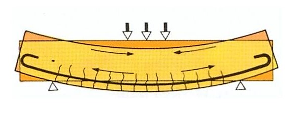
The vertical load induces compression in the upper layer of the beam and tension in the lower layer. The steel rebar is thus placed in the lower layer, but it can take over the tensile forces only after the concrete has cracked (micro-cracks!).
In a certain way the vertical load on the beam is taken over by the lower steel rebar like a wash line supports clothes. Obviously, a rusting wash line is not acceptable!
In a marine environment, salt water and associated chlorides (Cl– ions), sulphates (SO4– – ions), carbon dioxide (CO2), oxygen (O2), water (H2O) and other chemicals penetrate into the concrete by capillarity and diffusion and by convection through the micro cracks. These micro cracks are a problem because they allow the environment inside the concrete, eventually reaching the steel rebar. Obviously, the compaction quality and thickness of the cover layer located between the lower rebar and the under face of the beam (around 50 mm) is important, but micro cracks must exist in order to have the steel rebar working.
The result is that quite some RCC marine structures built in the past decades are already in really bad condition and needing very expansive repair works. Some coastal structures were supposed to last many decades, but are showing serious deficiencies after only 10-15 years! This is usually visible by traces of corrosion of the steel rebars embedded in the RCC structure.
This is inherent to the very concept of RCC and to the need for micro cracks in order to have steel bars taking over tensile forces. Some modern solutions like water repellents, additives with pore-blocking ingredients, cathodic protection, stainless steel rebars provide some relief.
This problem with RCC micro cracks does not exist with prestressed concrete (PCC). Instead of having a simple rebar as shown on the figure above, a steel cable (called “tendon”) is encapsulated and a prestress is applied to it. This induces compression inside the whole beam, as well in its upper layer as in its under layer. The vertical load on the beam thus induces additional compression in the upper layer (but concrete can resist that) and a tension counteracting the prestress in the under layer, but the latter remains under compression at all times.
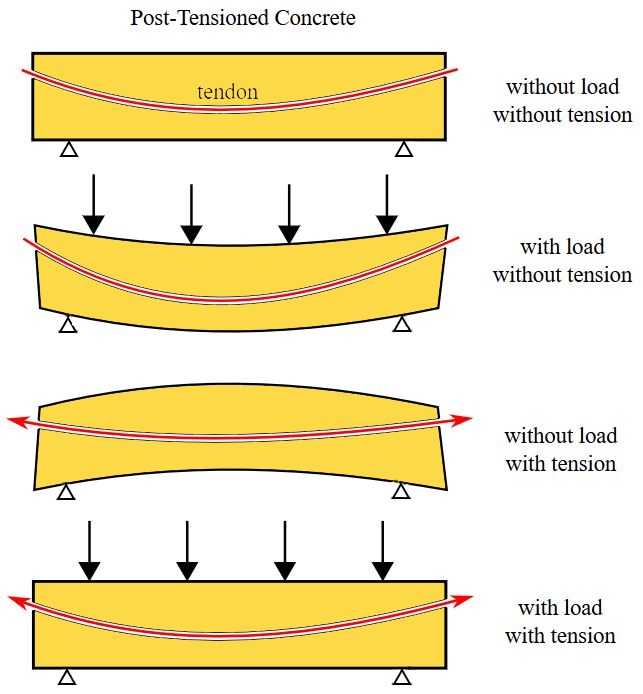
The vertical load induces tension in the lower layer of the beam. The prestressed tendon induces compression in the lower layer which counteracts the tension induced by the vertical load. (picture Wikipedia)
In this way no micro cracks occur and the beam is much more resistant to the environmental intrusions of chlorides and other chemicals, but the quality of the prestressing tendons is obviously of paramount importance: plastic ducting, grouting, cathodic protection, yield- and ultimate strength, stress relaxation. Further research on stainless steel tendons is ongoing.
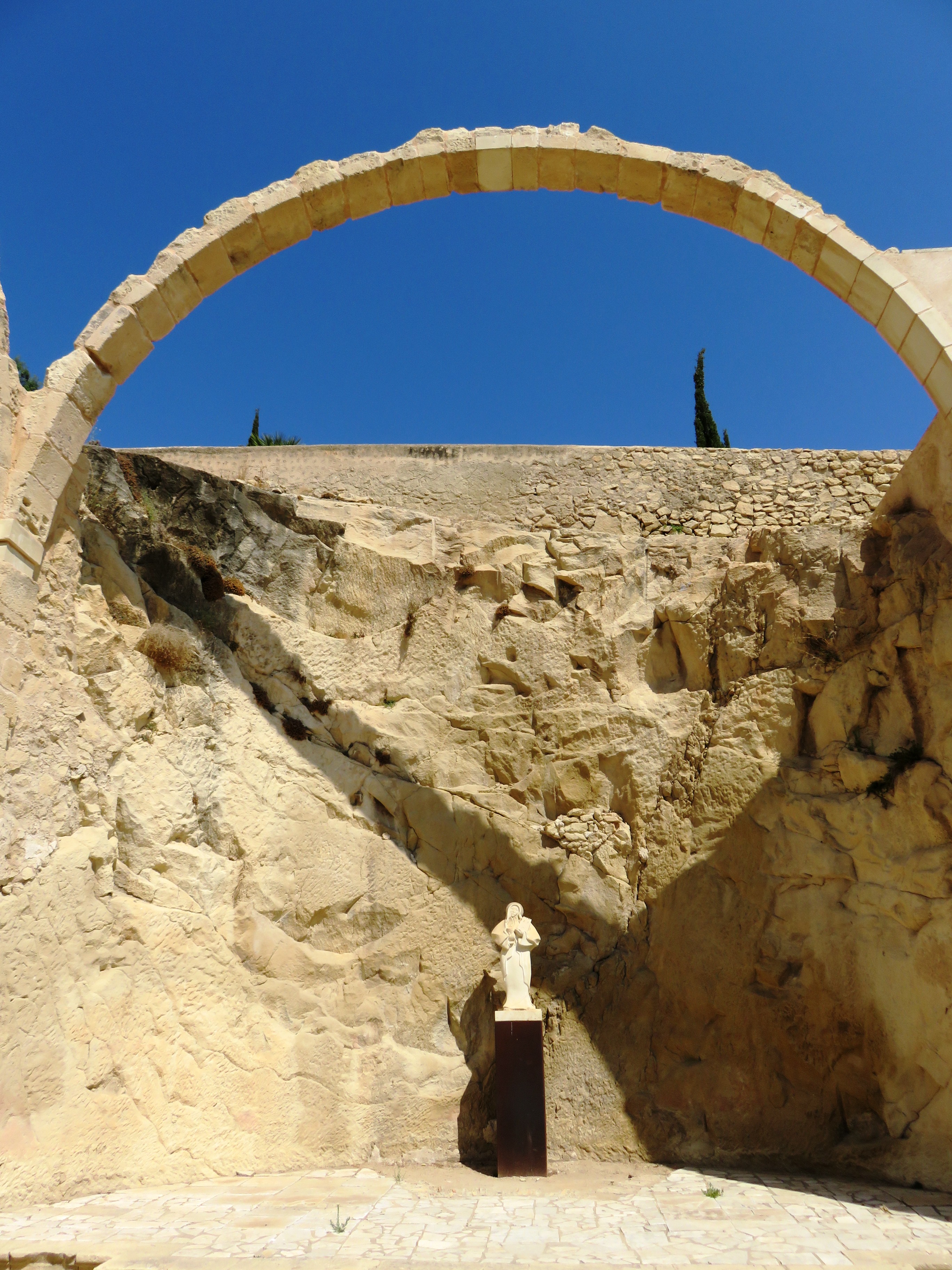
The concept of flexure and cantilever can be applied only to structures able to absorb traction (tensile) forces that are induced by flexure. It was seen with Vitruvius’ methods that wooden tie rods could be used, but wood does not resist in the long term (except when preserved in sediment). A similar system with granite columns can be seen at Ashkelon (Israel).

Granite is weaker than wood for traction, but resists in time as can be seen at Ashkelon in the remains of the crusaders’ bulwark built around 1150.

In figures: hard loaf wood can yield a tensile strength of around 100 MPa (10 kgf/mm2 ) (in the fibre direction!) while granite does not exceed 20 MPa.
For compression strength, everything is reversed: wood yields around 30 to 40 MPa, but granite is at 200 MPa.
It is sound to apply traction on wood and compression on granite.
According to Marie Jackson (in Oleson et al., 2014), the compression strength of Roman hydraulic concrete ranges between 2.5 and 8.5 MPa (modern concrete reaches 50 MPa and even up to 150 MPa for modern ultra-high-performance concrete). The tensile strength is reduced to about 1/10 of the compression strength. The latter being notably increased by steel reinforcement (steel has a tensile strength of around 200-300 MPa at the elasticity limit state), (see also: http://www.romanconcrete.com/romanconcrete.htm).
Very little is known about the use of iron in ancient structures, but Hadrian’s villa (ca. 120 AD, Tivoli, Italy) shows two exceptional pillar structures where iron bars (ca. 5 x 5 cm) have been used to support a lintel arch (kind of flat arch acting as a series of keystones) (Olivier, 1983; DeLaine, 2010[8]).
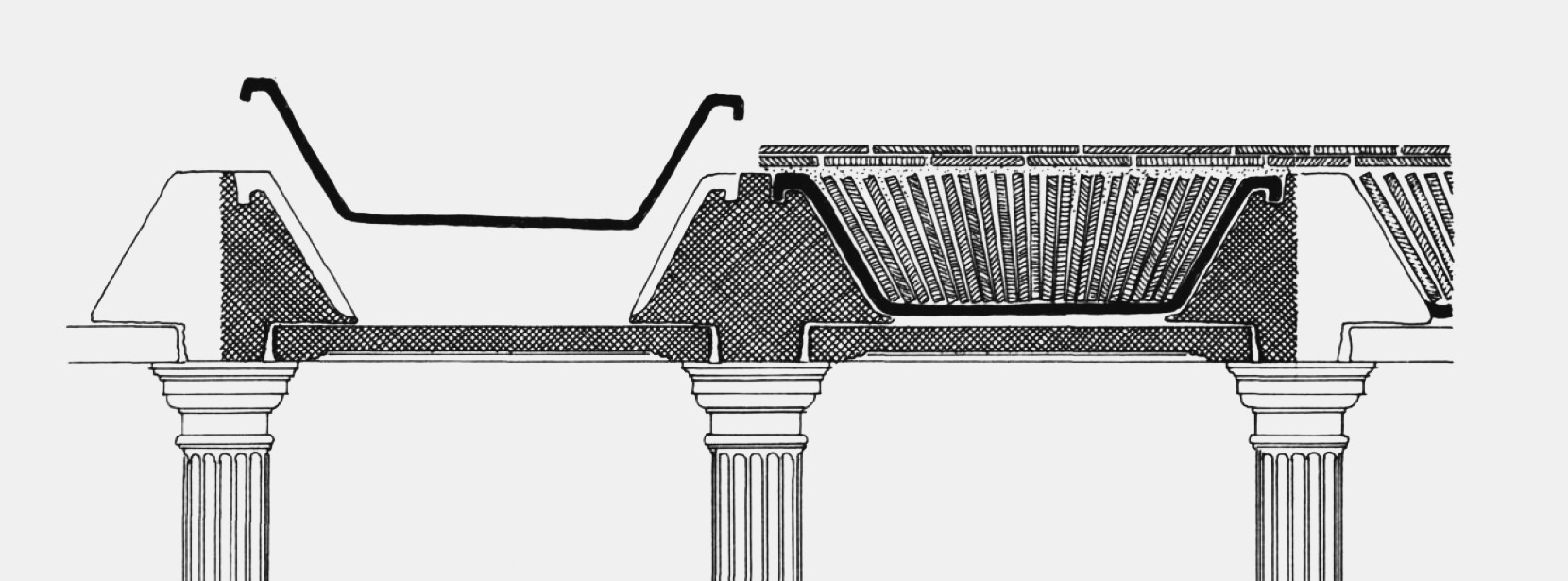
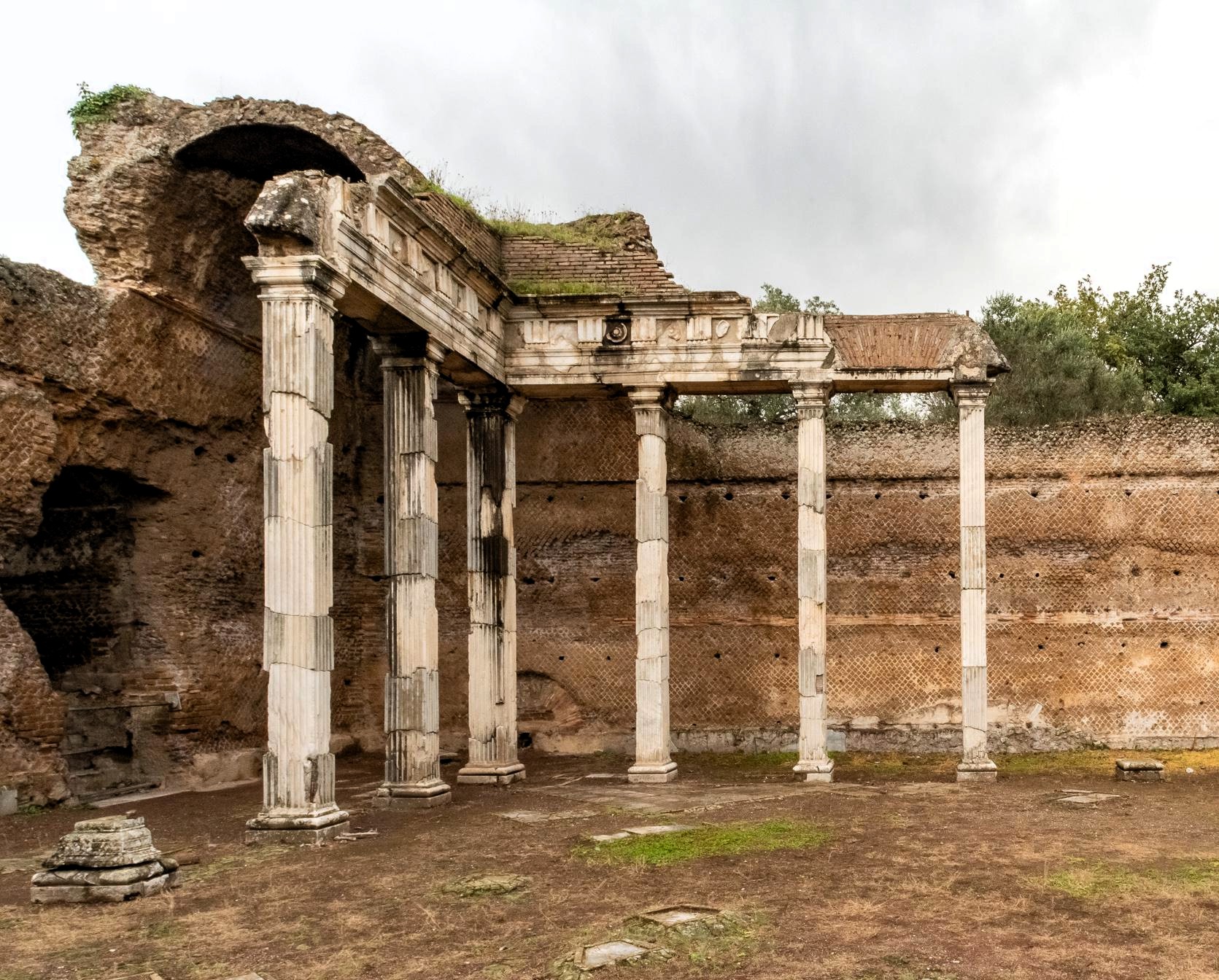
The resulting effect is a slender structure with a span width of ca. 1.8 m supported by small square 0.32 m pillars (compare with the Parthenon (Athens) where a ca. 2.3 m span is supported by 1.9 m columns!). These iron rebars probably allowed widening the span of the lintel arch somewhat. In addition, they probably improved resistance against earthquakes. However, the fundamental weakness of iron due to corrosion must probably be seen as the reason why so few iron-reinforced structures were built in Antiquity.
In addition, the concept of the arch had already existed for several millennia to solve the problem of flexure. Note that the Pantheon (Rome) had the widest arch (43.30 m) for nearly 2000 years and was only surpassed in the 20th c. thanks to reinforced concrete.
Horizontal chaining
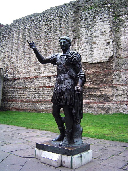
The horizontal columns of Ashkelon and Byblos remind the ashlar headers aiming at connecting two faces of a wall. For Opus Vittatum Mixtum walls, Jean-Pierre Adam (La Construction Romaine, 1995) speaks of “horizontal chaining” consisting of 2 or 3 layers of terracotta tiles (courses of bonding tiles) as can be seen on the London Wall behind the statue of Trajan.

It needs to be proven that these courses of tiles really act as bonding tiles, i.e. a structural element able to take over tensile strengths (todays’ chaining is steel reinforced).
It must therefore be demonstrated that terracotta not only resists at least as well to traction as the natural stone used in concrete, but also that the adherence of mortar on terracotta is better than on natural stone.
As far as tensile strength is concerned, we have mentioned granite above with a tensile strength of around 20 MPa, but sandstone and limestone are weaker with around 5 MPa. With a strength of 5 to 10 MPa, terracotta is in the same order of magnitude (but optimists would say “double”).
Concerning adherence, or bond strength, of lime mortars on terracotta and natural stone, we must go into some details, as this subject has not been much studied …
Measuring the bond strength of a stone or a brick on a layer of mortar is similar to measuring a shear stress. The unit of this stress is N/mm2 (MPa) like for traction and compression stresses. According to Pierre Nicot (PhD thesis “Interactions mortier-support”, Toulouse, 2008) “bond strength can be defined as the force required to separate two constituents” and he explains that bond strength between mortar and a support can be chemical and mechanical. The latter involves porosity of the support, its water absorption capacity, etc. Dare we make an analogy with welding of metals?
These comments lead us to consider the tests defining these parameters. Some tests are normalised under masonry test procedures (EN 1052):
- Part 1: Determination of compressive strength (BS, CSTC),
- Part 2: Determination of flexural strength (CSTC),
- Part 3: Determination of initial shear strength (CSTC, BS),
- Part 5: Determination of bond strength by the bond wrench method (CSTC).
It can be noted that the ‘pull-off test’ and ‘crossed couplet test’ are missing to obtain the tensile bond strength, but according to Wikipedia on its Mohr’s circles page “the force required to tear off atoms from each other is much larger than the force required to make them slide over each other”, which means that resistance to initial shear stress (also called ‘cohesion’) is lower than the resistance to pure tensile strength. The test of interest here is thus the one described in Part 3 of the norm EN 1052. This test is conducted by pushing out a brick pinched between two others (‘shear triplet test’) with an interpretation using Mohr’s circles which is well known in the field of soil and rock mechanics.
Thomas Zimmermann & Alfred Strauss from the University of Wien[2] provide initial shear strengths of only 0.03 MPa for lime mortar without cement, and 0.21 MPa for mortar with cement.
Adrian Costigan & Sara Pavia from the Trinity College Dublin[3] say that bond strength is very important for the compressive strength of the whole masonry structure. Their results can be summarised by a bond strength ranging between 0.1 and 0.4 MPa (depending on the tested types of lime mortar), and a compressive strength ranging between 2 and 8 MPa (that is 20 times more than for bond strength).
Today’s mortars (e.g. Beamix 341 or Weber.mix MM319) also claim bond strengths on brick in the order of 0.1 to 0.2 MPa, and even 0.3 MPa. These values can be increased (by a factor 10!) with special adjuvants.
So far for bond strength between mortar and brick. But how about bond strength between mortar and natural stone?
At the beginning of the 19th century, Louis Charles Boistard conducted tests on the bond strength of natural stones on lime and sand mortar with the following conclusion: “bond strength of lime and sand mortar can be estimated at at least 1500 pounds/sq feet” that is around 7000 kgf/m2, or 0.07 MPa after 18 months of hardening.
G. Vasconcelos & P.B. Lourenço from the University of Minho[4] performed tests on wall sections of 1.0 x 1.2 m2 and found a diagonal shear stress of 0.05 MPa for masonry with ashlar and 0.11 MPa for masonry with natural rock; the first having more linear joint planes than the latter, which may perhaps explain the different test results.
M. Corradi & al. from the University of Perugia[5] performed similar tests for various types of wall and found shear stresses around 0.08 MPa.
These figures tend to prove that bond strength on bricks (0.10 to 0.40 MPa) is indeed higher than on natural stones (0.05 to 0.11 MPa).
It seems that we may carefully validate the hypothesis that courses of bonding tiles located in the lower sections of massive structures like bulwarks and donjons increase the internal cohesion of the lower part of the structure.
References
[1] SEYMOUR, L., et al., 2023, “Hot mixing: Mechanistic insights into the durability of ancient Roman concrete”, Science Advances, 9, eadd1602, New York, (13 p), https://www.science.org/doi/10.1126/sciadv.add1602
and https://www.youtube.com/watch?v=dzarpnLffHY
[2] ZIMMERMANN, T. & STRAUSS, A., 2011, “Variation of shear strength of masonry with different mortar properties”, North American Masonry Conference, Minneapolis, 2011.
[3] COSTIGAN, A. & PAVIA, S., 2010, “Influence of Mechanical Properties of Lime Mortar on the Strength of Masonry”, Historic Mortars Conference, Prag, 2010.
[4] VASCONCELOS, G. & LOURENÇO, P.B., 2006, “Assessment of the in-plane shear strength of stone masonry walls by simplified models”, Structural Analysis of Historical Constructions, New Delhi, 2006.
[5] CORRADI, M., et al., 2003, “Experimental study on the determination of strength of masonry walls”, Construction and Building Materials, 17, Elsevier, 2003.
[6] GINALIS, A., 2022, “The So-called “Küçük Liman” on the Firuzköy Peninsula”, International City and History Symposium on Avcilar, (p 143-161).
ARTIOLI, G., SECCO, M., ADDIS, A., 2019, “The Vitruvian legacy: mortars and binders before and after the Roman world”, in: The Contribution of Mineralogy to Cultural Heritage, EMU Notes in Mineralogy, Vol. 20, (p 151-202).
BISCONTIN, G., BIRELLI, MP., ZENDRI, E., 2002, “Characterization of binders employed in the manufacture of Venetian historical mortars”, Journal of Cultural Heritage 3, Elsevier, (p 31-37).
PINTER F., et al., 2011, “Brick-Lime Mortars and Plasters of a Sixteenth Century Ottoman Bath from Budapest, Hungary”, Proceedings of the 37th International Symposium on Archaeometry, Springer-Verlag, (p 293-298).
[6a] GERTWAGEN, R., 2024, “Byzantine Imperial Policy Towards Building and Maintaining of Ports in the Eastern Mediterranean in the 6th Century AD and the Technology Involved”, in edt. A. Ginalis, Harbours of Byzantium, The Archaeology of Coastal Infrastructures, Archaeopress Publ., Oxford, (p 1-33).
[7] OLESON, J., BRANDON, C., HOHLFELDER, R., JACKSON, M., 2014, “Building for Eternity – The history and Technology of Roman Concrete Engineering in the Sea”, Oxbow Books, (327 p).
[8] OLIVIER, A., 1983, Sommiers de plates-bandes appareillées et armées à Conimbriga et à la Villa d’Hadrien à Tivoli, MEFRA, 95, p 937-959.
DELAINE, J., 2010, Structural experimentation: the lintel arch, corbel and tie in western Roman architecture, World Archaeology, 21, p 407-424.